Definitions
Contents
Access
Access is used to configure the protocol and username/password used for accessing Equipment. Plugins can use these informations in order to get credencials for listing and configuring Equipment.
You can insert many different protocols for each Equipment, like telnet, ssh, snmp etc.
Administrative Permission
Security functions that are used to allow administrative system functions or equipment configuration functions. These permissions are configured per User Group.
Notice that in order to do equipment configuration functions, the User Group has to have the respective administrative permission AND permissions on the Equipment Group.
Environment
The environment defines a logical part of the infrastructure, usually a broadcast domain. It can be divided in 3 parts: “Divisao_DC”, “Ambiente Logico” and “Grupo Layer3”. It is expected to have all vlans in a environment routed in the same gateway/router.
I.e. In the picture below, you can see 5 different envinronments, represented by different colors:
- The Red has vlan range from 11 to 20 and Equipment R1, R2, R3 and SR1.
- The Blue has vlan range from 21 to 30 and Equipment B1, B2, B3 and SR1.
- The Green has vlan 31 and Equipment SR1 and Router.
- The Yellow has vlan 20 and Equipment SR2 and Router.
- The Orange has vlan ranges from 15 to 19 and from 21 to 40, and Equipment O1, O2 and O3 and SR2.
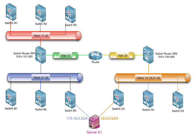
example topology
Notice that, as you have a common equipment SR1 in 3 environments Red, Green and Blue, you cannot have vlan numbers that overlaps in them. The same applies to Yellow and Orange environments.
As Orange and {Red, Green an Blue} have no equipments in common, they can have vlans that shares the same numbers.
This is automatically considered by Globo NetworkAPI when you configure your environments and their Equipment.
You can also have a server like S1 that needs to connect to more than environment. In this cases, you have to configure a Filter for those environments.
Equipment
Equipment represents any object in the infrasctructure that has to be documented. Routers, switches, patch panels, servers, load balancers, virtual servers etc. Equipments have a type, a “brand” and a “model” in order to categorize it. They can also be arranged in Equipment Group.
Equipments can have IP (IPv4/IPv6) and Interface and can be associated with an Environment.
In example topology above, server S1 has IPs 172.16.0.5 and 10.0.0.5 and is part of 2 environments, Blue and Orange. Switch B1 does not have any IP address, but it is part of Blue environment. SR1 may have hundreds of IPs and it is part of 3 environments.
Equipment Group
Equipment Group is used for access restrictions on Equipment.
In order to be able to read/write configurations for an Equipment, a User has to be in a User Group that has the necessary permissions in at least one Equipment Group that the specific Equipment is part of.
So, in order to be managed, an Equipment has to be part of at least one Equipment Group.
Equipment Type
This is field for categorizing the Equipment. It is also used in Filter.
Filter
Filters are used to permit an Equipment of a specific Equipment Type to be part of more than one Environment that has overlapping vlans and/or networks.
In the example topology above, server S1 should be part of two environments that have overlapping vlan numbers. In this case, there should have a filter that has the server S1 Equipment Type applied in both environments, Blue and Orange. It is recommended not to create filters with switches or routers.
IP (IPv4/IPv6)
Represents the IPs allocated for every Equipment in a specific Network. You can allocate the same IP to more than one Equipment in the same network (clusters, gateway redundancy protocols etc). There is no limit on the number of IPs an Equipment can have (if available in Network).
The allocated IPs are used for documentation pourposes and for automatic allocating of newly unused IPs.
Interface
Represents the physical interfaces that Equipment may have and the connections between them.
- You can represent patch panels in 2 ways. Generic patch panel or mirrored patch panel. When 2 patch panels are connected by their back connections in a organized way (the same interface numbers are correlated), you can represent them as a single Equipment, a mirrored patch panel. In other cases, you can represent each panel as a separated Equipment, like a generic patch panel.
- Patch panels has for each interface, 2 connections. The “Front” and “Back” connection. You can define each side as you want.
- Only patch panels have “Back” connections. All other equipments should have only “Front” connections.
Figure below show some examples of physical interfaces:
example interfaces
example connections with a mirrored patch panel
example connections with generic patch panels
Some equipments may have a front and back connection (i.e. patch panel) and some equipments only have 1 possible connection (ie network interface card on servers, switch interfaces etc).
Interfaces are used for documentation pourposes and to locate a switch port that a specific server is configured when you want to change that server inteface configuration on switch side. Interfaces that should not be configured in any case by the system should be configured with “protected” flag.
Network
Represent the layer 3, IPv4 or IPv6 address range.
As it is a different layer, althought not recommended by IP networking best practices, you can have multiple IPv4/IPv6 networks in the same Vlan.
As Vlan and Environment, you cannot have two overlapping networks (same length or subnets/supernets) in the same environment. The equipments should not be able to treat that, but you can have those in different environments. I.E. in picture example topology you cannot have overlapping networks 172.16.0.0/24 and 172.16.0.128/25 in Blue, Red or Green environment at the same time, because the same switch router supports all Layer3, but you can have 172.16.0.0/24 on Blue and 172.16.0.128/25 on Orange environment for example.
Network Type
Used for documentating purposes only. You can for example tell that Network of a specific type are used for point-to-point links, or for internal usage only, networks for NAT only etc.
Plugin (Roteiro)
The files used by the Scripts for performing a task on specific Equipment. Each plugin have a type to be categorized. You can write your scripts and how they look for your plugins, but is recommended that the plugin name be the file name used.
The plugin type is used for calling the correct Scripts in order to do that type of configuration.
Scripts
You can create scripts for doing anything in your environment. We recommend making them for a generic feature, and call a Plugin (Roteiro) from them to make equipment/brand specific syntax commands.
You associate a script with a specific Plugin (Roteiro) type and associate the Plugin (Roteiro) of that type to the Equipment. This way you can perform several tasks on different Equipment brands/models with the same plugin.
Template (ACL)
When you configure an Environment, you can define a base model for the access lists (ACL) for every interface vlan (SVI) that you create there. This model is the template. It is a text file with keywords that are replaced with the network/Ips created for those networks.
You can define a template for IPv4 and another for IPv6 Network for each Environment.
User
An account for a client to authenticate. You can use a locally stored password or configure to use LDAP authentication.
User Group
User groups used for access restriction. All permissions are based on user groups. There is no way to give a permission directly to a User.
Vlan
Represent the layer 2 Vlans on equipments. See Environment for restrictions on vlan numbering.